
Search This Blog

Badger

Badger
In Greenland

Iron Bark

Iron Bark
Under full sail

Fantail

Fantail
At Russell Boating Club's Tall Ships Regatta

Blue Water Medal

Blue Water Medal
Blue Water Medal

Books By Annie Hill

  • Brazil and Beyond
  • Voyaging on a Small Income
Showing posts with label Practical Junk Rig. Show all posts

01 November, 2020

Building a topmast and making a yard

 Well, these two jobs have occupied most of October.  Before I really got into them, however, I finished fitting the hoop.

Gluing it in place was a fiddly business.  Ideally, I would have attached it to the frame 50 mm abaft where it ended up, which, indeed, was my initial intention, but it interfered with the wind vane.  I could have made a new windvane.  I decided it was easier to move the hoop further forward.


And here it is in place, awaiting paint.  It's fairly sturdy, as long as no heavy person decides to swing from it.  One can't legislate for every eventuality.


I bought the Oregon for the mast when I started building the boat.  (In NZ, Oregon is used to discriminate the high-quality, imported wood from the locally-grown, Douglas fir.)  It's beautiful wood, very fine grained and straight.  David had suggested I build a hexagonal mast.  In retrospect, I wish I had bought 8 boards: it would have been easier.

When making a birdsmouth mast with six sides, the angles need to be 30° and 60°.  I puzzled over this for some time before deciding the easiest thing would be to cut up some pallet wood and make a mock-up from this.  That would allow me to work out how to do the second cut.


I couldn't get the table saw blade to go down, so in desperation I went to Master Boatbuilder, Noel Barrot, and asked him for some advice.  He very kindly spent the best part of a morning, dismantling the table and splashing oil around with joyous abandon after I had removed the grunge of decades from various orifices.  The blade moved up and down with wonderful ease and precision after this.  I then cut the first angle on the pallet wood and discovered that by turning it on edge, I could then make the second cut of 30°.  It was gratifyingly straightforward.


All the information I needed to work out angles, thickness, strength (a bit of a closed book to me, I have to confess), etc I gleaned from the Duckworks site: Birds Mouth Spars revisited.  This also gave me the dimensions for the tapered top of the spar, which was different from what I had assumed, which saved me from a real blunder. I discovered this site from Gary Pick's excellent article in JRA Magazine no 57.  Gary also very kindly answered several emails from me while I was groping my way forward.

Having cut up the pallet wood, I cut it into 6 pieces and roughly put them together to see how this concept works.  


With my heart in my mouth I prepared myself for the Real Thing.  Fortunately for me, Gordon was passing on his way to Auckland and, yet again, allowed himself to be shanghaied into not only getting the 6 m tube down and onto a bench alongside the shed, but helping me machine the Oregon.  Another reason I was glad that he was there was that the pieces of wood, well over 4 m long, wouldn't fit through the gap in the stairs, when they were on edge.  This meant the removal of one of the stairs, which Marcus had secured with every intention that it should stay in place.  Wielding a hammer to good effect, Gordon not only managed to remove it, but also to replace it once the job was done.  I had paid about $1,000 for this wood, so it was, to say the least, nerve-racking, sending it through the saw.

However, it all went without a hitch and I soon had a stack of nicely-milled timber awaiting the next move.


Here you can clearly see the birdsmouth.  You can also see why the 45° would be easier to work with than the 30° and 60°.  The smaller joint is a bit more fragile than ideal.


Gordon carried on his merry way, and I cleaned up all the grooves.  Noel suggested knocking the back off the part that would adjoin the groove, as well, to ensure a better fit and plenty of glue.


The next stage was to taper the staves.  Ideally, I would have started the taper from 600 mm up, so that the base would have been straight and easy to put into the alloy tube.  However, I didn't see how this could be glued together so with the aid of the invaluable website, worked out what the base should be and marked out a straight taper from top to bottom.  My little battery-powered circular saw did the work.  I cut the 35 mm staves in three stages of increasing depths, but the poor little saw still struggled and it had to have a rest at the halfway point for its battery to be recharged.  As I was still finding the whole business quite stressful, terrified that I would make some irremediable mistake, these enforced breaks were good for me, too.


The next job was to glue up the staves.  I didn't want to do it in one hit, because I wanted to put a wire up for the masthead light and I also wanted to be able to check that (at least half!) the joints had glued together properly.  At first, I planned to do it in two stages and then glue the two halves together, but then I thought that only a little distortion could make this very difficult, so decided to do it in just two stages.


The first 2 pieces could be temporarily clamped while I prepared the third.


Holding the three pieces secure was something of a challenge, and this is one of the cases where an 8-sided mast would have been a lot easier.  Clamps simply wouldn't work and, if anything, tended to distort the shape, however carefully wedged.  I had discovered this as soon as I had tried a dry fit, so in the end decided to use cable ties.  I couldn't exert that much pressure - or I ended up back at the clamp situation.  This is one of the situations where epoxy is superior to most other glues: it doesn't require any clamping pressure to speak of.  Anyway, it all went together fine.


Once the epoxy had set, I tried a 'dry run' to check that everything went together well and it did.  The third piece slid in easily and fitted acceptably.  However, the act of sliding it would tend to remove some glue, so I would have to be generous.

I coated the inside of the three pieces that were to be fitted next.


I also coated the inside of the already-glued mast and laid the wire for the tricolour light along it.  With wire being relatively stiff, you might think it would be easy to slide it in after the event.  However, as I have learnt the hard way, it isn't and with the very real chance of lots of glue drips at the next stage, I reckoned that there would probably be too many snags to make it easy to send a mouse down, too.


Again, I assembled it all with lavish amounts of glue, but as so often happens, in spite of there being a very good fit the first time, when it came to the final job, the 'shutter plank' was a struggle to get right.  Don't ask me why.  In fact the very bottom of the mast ended up a far from perfect hexagon and there were gaps along a couple of the glue joints.  However, there was nothing that could be done about it, so I just secured it all together as well as I could and hoped I'd be able to sort it all out after the event.


Noel, kindly mentoring this whole business, told me that the next task was to turn the six sides into twelve.  Google was no help at all here: the only reference I could find to a six-sided mast was due to the fact that the fellow writing it didn't know a hexagon from an octagon.  With eight sides, you can use Pythagoras to work it all out, with six you have to be a little more empirical.  Tony from the boat next door, lent me a chalk line and I carefully assessed the mast by eye (not at all my strong point) and marked where I should plane to.


Noel had also suggested that at this stage, instead of going for a straight taper, I should go for a spar taper (which I assume is the same thing as the barrel taper, mentioned in Practical Junk Rig)    Supposedly it is more pleasing to the eye, but quite honestly, I can't see the difference.  Still, the Master was helping and the least I could do was follow his advice.


At the early stages, I could use a power plane, but before long I was using a hand plane.  I'm afraid Noel was somewhat unimpressed at my attempts at sharpening my planes (I can't say I am surprised, it is still a skill I have to perfect) and kindly took them off with him to hone to a scary degree of sharpness that I could only envy.


The object of the exercise was pick several points along the mast, work out what diameter they should be and then keep planing, turning and measuring.  The initial part of the shaping was done by taking a long plane from one end of the mast to the other, in one sweep 5 times.  Then I turned it and did the same on the next face and so on.  Then it was all measured and as time went by, I could take more (or less) off each face until the mast became more even.  


I used a hole saw to make patterns and Noel lent me calipers to check further down the mast.
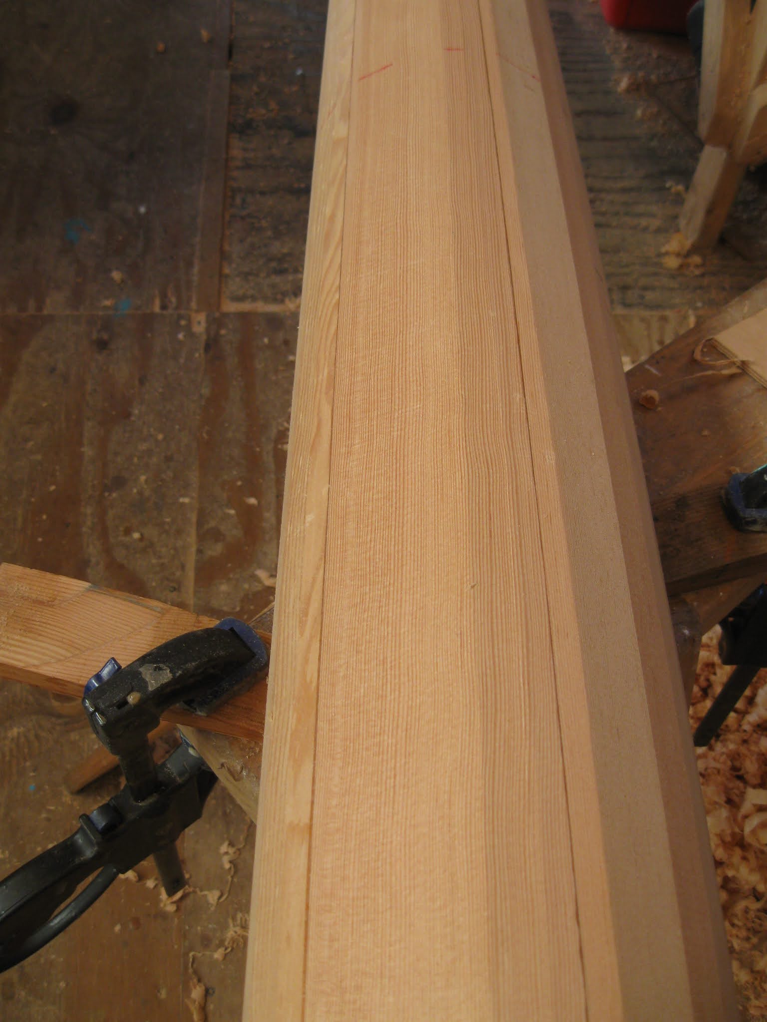

Finally, I had 12 even sides.  Then came the best bit: Noel lent me one of his treasured wooden planes (found in the Falkland Is), which has a radiused base so that it takes off all the corners and produces a curve.  It was a lovely thing to use.


By putting chalk on the inside of my plywood patterns, I could find the high spots and attack them individually until the whole mast was smooth and even.


The last little high bits took the longest to smooth down, but finally I decided that it was good enough.

Of course, I now had a nicely tapered spar, but the base of it was far too big to fit inside the alloy tube.  So the next job was to shape that.


I carefully marked it, measuring from the top of the mast and then roughly planed the lowest part to within coo-ee of the desired 142 mm.  Noel's suggestion was to use a router to take off the bulk of the excess wood and then finish it off with a plane.  Noel is not a man who lightly recommends the use of power tools, and I find using the router freehand a bit daunting.  However, I gave it a go on the principle that if I did make a big gouge where I shouldn't, I would at least be able to fill it again.


I actually found it a bit easier than I had anticipated and the router only ran away with me once.  Much planing followed, both along the mast and, at the top, across the grain, which left a bit of a mess that I cleaned up with my block plane.  I had made another pattern with a 142 mm hole saw, which was invaluable for getting this section shaped.


Finally, the spar was ready to sand.  Noel told me about using a long strip of snanpaper and pulling it back and forth around the masts circumference to remove the excess and again work on any high spots.  It was insanely efficient.  It was also an exceptionally good workout!

With the mast sanded, I could now try it for size.  


To my gratified astonishment, it slid gently into the alloy tube at the first attempt.

I have to say, I did a rather better job with this one than I did on Fantail.  On the other hand, I also had plenty of wood - and Noel!


As I mentioned earlier, some of the joints weren't all they could be.  I had tilted the mast, top down, and run glue down the inside where one joints seemed to be more open than I was comforable with.  Shining a torch down the inside, most of the joints looked OK, but there were still a few places where the glue had blown bubbles, dripped out or generally not done as it should, so I went back and filled them all.  I had been concerned that maybe some of these holes were serious, but they were filled easily, so I think the mast is probably sufficiently well stuck together.  


And as added insurance, I put a 'Band-aid' of glass and epoxy around it.  In fact, the glass and epoxy is to make it nice and hard for the ropes that will pass around it, moving constantly when the boat is under way.

At the very start of this project, my friend, Paul, at All Marine, gave me a roll of fibreglass.  Over the years, several friends have taken advantage of it for covering masts, dinghies, etc and I was hoping that I would still have enough for covering the mast.  When I had finished, here was about 50mm left over.  Thank you, Paul!!


I also put some fillets inside the mast up to the 'partners'.  The Duckworks site reckoned that the walls were thick enough, and equally to the point, so did Noel, but those additional fillets gave me an extra sense of security.


The whole spar was coated again and is now ready for sanding and painting.  


I had always hoped that there would be enough Oregon left over to make my yard.  There is a school of thought that a 'fat oval' is better than the yard suggested in PJR and I debated whether to make one of these (using my newfound skills to produce a barrel taper) or to go for the classic design out of the book.  As it turned out, the wood that I had was only suitable for the latter, but I am actually perfectly happy with going that route.  After all, this is how we made the yards on Badger, and to the best of my knowledge and belief, they are still going strong.


I roughly shaped the boards before gluing them together and then knocked off the majority of the excess with a power planer.  After the initial glue up, I was a bit concerned that I had made a mistake.  The yard weighed a ton.  I like a bit of weight to bring the sail down, but this was ridiculous!  However, I carried on planing and shaping and in the end was delighted at how light it has turned out to be!  Heavy enough to bring the sail down: light enough to hoist without too much effort.  Just what I wanted.


I finished the job by hand, again surprised at how good a finish one can achieve with hand planes, so that the final sanding takes only a few minutes.  I rather enjoy looking at the 'traditional' yard.  It brings back many happy memories.  I wonder if I will be able to resist the temptation to varnish it!


I swept up and filled a large bin bag with the shavings.  There was another half bag in addition to this.  Very expensive wood shavings!


06 September, 2020

More on bilgeboards, rudders and now ... self steering. Plus a bit of paint.

I concluded my last post with the less-than-welcome discovery that the bilgeboards could not be rigged as planned.  Obviously a Plan B was required.

 If you look carefully at the photo, you can see what the problem is.  A block is required on deck to haul the bilgeboard up.

If it is fitted on the piece of teak, intended for that purpose, the rope will catch on the plastic strip at the after end of the board.  The obvious thing to do was to put the blocks on post, which would bring them further inboard.

Some years ago, I was given some fibreglass stanchions.  They are very strong and well made, but at 33mm diameter at the base, looked far too large when I offered them up for their intended purpose.  However, I reckoned they would be ideal for this job, and laminated up some leftover teak decking to make a base for them.

These bases were glued to the decks, joggled around the teak already there.

The stanchions were fitted into holes that were sunk well into the bases, using a hole saw.  Extra glue was poured in from the top to ensure a really substantial "root" had been achieved.

The posts in place.  In the background is Blackie, a feral cat that thinks the shed is her home.

I capped off the posts to keep the rain out and could then rig the blocks for raising and lowering the boards.  Well, as it turns out, lowering them.  With no water to float them raising them is impossible, at present: the slope of the cases plus gravity makes for too much resistance.

While this had been going on, I had decided to get my pram hood frame made up.  There are very clear drawings in Practical Junk Rig, and I took my copy along to a local company that specialises in making stainless steel stuff for boats.  I showed him the drawing, said what I wanted, gave him the semi-circular piece of wood that I had already made and asked him if he wanted to keep the book.  He photocopied the relevant page and gave it back to me.  I asked him if he really understood the concept and he looked at me as though I had crawled out from under a stone.  Of course he did.

Well, apparently he didn't.  Not only did he make the frames far too heavy - 18mm stainless steel instead of the 12mm that would have been more appropriate, he made the hinge/connector way too big.  You can see it in the top left corner of the photo.  Made out of 3mm material, it was impossible to bend to match the wood, and moreover, it was so big that it extended well beyond the hemisphere.  And the frames didn't stack properly.  I am not the cleverest of people when it comes to following a drawing and it is a slow and painful process for me to reproduce something.  However, I worked out a scale from the book and made a pattern out of 4mm plywood in about half an hour.  I then adjusted it until I could get the somewhat altered frames to fit.  I couldn't afford to get the whole thing made again, and there is nothing actually wrong with 18mm for the frame.  It's just unnecessarily heavy.

I took my pattern to another shop (I am completely feeble about going back to complain to people) and got them to make what I wanted.  They really couldn't go wrong and I drilled out the holes myself.  Here is the framework in place.

And this is with the frames folded down.  At the end of the day it is a very acceptable job and I give grateful thanks to the good friend who gave me some funds to make this possible.  I shall always think of it as his pram-hood.

Joining the rudders together has been something that has puzzled me for a long time.  There's all this blather about Ackermann steering which is all to do with car wheels, but apparently applies to rudders, too.  Then the rudder bar has to allow the engine to lift.  After much cogitation and some discussion with The Great One, who spelt it all out to me in words of one syllable, I decided that the bar would be best fitted abaft the rudders on small 'tillers', attached to the rudders.  Some of my invaluable old kauri was sawn up for this purpose, and glued so that the tillers had a small wedge on them, according to Mr Ackermann's theories.  I've already forgotten exactly what they are!

The next job was to sort out the self-steering gear.  More multitasking!  It's really rather stressful, in truth, and leaves me little energy for other things.  The Great One, once more had come up trumps, you will recall and really, all I had to do was to make the connections and a wind vane.  I had made little tillers for the trim tab rudders, and made the connection between the vane and the nearest (port) tiller from Tufnol.  While I am perfectly sure that David made everything correctly, I am never quite sure that I have done an equally good job, so I have made several extra holes in both so that I can adjust the trim of vane to trim tab if necessary.

I think I mentioned about having to put on yards of masking tape - one of my least favoured jobs, so that I could start painting.  Anyway, I spread the red paint with gay abandon, but came to regret not putting on any undercoat.  The red polyurethane doesn't cover that well (and, to be fair, it says so on the lid) and a base coat would have made it all more even.  Five coats were required to get an even (ish) appearance.  I shall not make the same mistake with the other colours!

Another issue that has been tasking my poor brain for, literally, years, has been the tiller(s). Having somewhat reluctantly concluded that one tiller was simply not going to work, I have accepted that I will have to have two.  However, it's bad enough having one tiller in the cockpit at anchor, but two is beyond a joke.  The obvious thing is to hinge them up and I was sure that this would be my solution until it sank into my tiny mind that there is to be a thundering great seat across the lute, over the rudders.  This would obviously prevent them lifting.  Always, in the back of my mind, is the fear that I might have to clear harbour, one dark and stormy night, with no notice.  The idea of removable tillers is therefore anathema to me, but finally I had to accept that if I wanted to be able to have a clear cockpit at anchor, then I will have to be able to take the tillers out.  And besides: I don't expect I'll be sailing in wild places that often!

The next question was how to fit the tillers and all I could really come up with was some sort of box into which they could slide in or out.  I couldn't put the tillers on top of the rudders, contained between cheeks, because of the trim tab tillers.  I didn't want anything too clumsy and the best I could come up with was fitting them into some box section metal.  I managed to run down some aluminium of very nearly the dimensions of the section that I had already laminated for my tillers (before I realised that they couldn't be hinged!).

Having finally made my decision, I cut the laminate in half and shaped the tillers.  The laminates make them strong, and although they don't look that big, they certainly compare favourably with solid tillers on boats of a similar size and, of course, the rudders are not that big.  I am a great believer in reefing out weather helm: I am sure they will be amply strong.

The plan was to screw the cases on to the side of the rudders, bedded on Simson's Marine Glue.  It is possible to glue alloy with epoxy, but very messy.  I intended to leave two large screws in place anyway, so the Simson's should be more than adequate.  A bolt, with an R clip to secure it, will pass though both tiller and rudder head.  I scarfed a piece of purpleheart to the base of the tillers because it is both harder and stronger than teak.  I then coated them with epoxy and graphite powder.

While I was working on the rudders, I decided to fit a couple of stops.  I have never had rudder stops on a boat before, and have often felt that they would be a good idea.  Time will tell.  On this photo, you can also see the long bolt that fits through the tiller and its case.

I fitted the shaped tillers to check that everything works.  They are easy to remove and replace. They lie neatly outboard on the upper seating and don't interfere with anything.  Once the alloy is painted, it will be less obvious.  I admit that this isn't the prettiest of solutions, but it is practical.

Meanwhile, I was carrying on with the self-steering gear.  I bought some 3mm plywood for the vane and cut it to the same shape as the sail will be, which I think looks rather nice.  I glassed one side, to stiffen it a little.  I didn't want to add the extra weight of glassing both sides.

The trim tab tillers also need to be joined, so I made up a little bar from offcuts of teak.  I am getting a bit short of suitable timber and reckoned that the laminated teak would be both strong and light.  I had epoxy mixed anyway, to coat the bottom of the seat.

The reason I was trying to keep the vane light is because it is necessary to counterbalance it in order for it to respond to the wind as is required.  I added struts to the plywood to attach the vane to the post down to the self-steering mechanism

and to support the counterbalance weight.  I was following David's drawing, but when I realised how much lead was required, I rather wished I'd made the lower arm a bit longer.  Real boatbuilders would have melted scrap lead to an appropriate shape.  I'm terrified of doing that, so went and bought a couple of 500 gram dive weights and a variety of fishing weights to trim it accurately.  I glassed the big weights to the lower arm of the wind vane.

I then put it onto the upright and tried adding small weights until the vane balanced.  Another 2x8oz and 3x1/4 oz weights were required.  The last 1/4 oz made it a little nose heavy, but I still had to add paint to the vane.

I fitted the self steering to check that it all seems to work - and to get it out of the way until I would paint the vane!
Finally the last coat of red paint was on and I covered it with clear polyurethane to protect it from the sun.  Counter intuitive, I know, but the commercial, clear two-part polyurethane that I use as 'varnish', has better UV inhibitors than the coloured paint!
I finished off varnishing around the stern and waited for it to harden off so that I could affix the solar panels.
Gordon was painting his dinghy, so I filched the tag end of his white paint to cover the small pieces of wood that will serve as dividers between the colours on the cabin sides.
I had been discussing my bow rollers with a friend and it occurred to me that I might as well fit them.  I've been putting it off because it's a bit of a squeeze getting past them, but as I won't be lugging pieces of wood around 'upstairs' any more I decided to secure them permanently.
The next stage was to prepare the cabin sides for undercoating and I decided to do the battens for the sail at the same time.  There are seven battens in total, including the boom, and as they are jointed, that means 14 altogether.  They take up a lot of space, laid out flat.
Then there was another long day spent masking off the red paint so that I could undercoat the cabin sides.  Blackie seems to have got herself into the photo again.

Yay!  Here goes the first coat of undercoat on the cabin sides.  This stuff covers wonderfully, as you can see, and has a slight sheen so that it shows all the bumps and hollows.  I'm actually very pleased with how fair the hull is.  There are no fillers apart from what I used over the scarf joints before covering the hull with fibreglass.  The undercoat is International Perfection.I might have used if for the top coats, too, except for the fact that the range of colours is so limited.  It is certainly the easiest two-part polyurethane I have used for producing an acceptable finish.

Acceptable to me, perhaps I should say.  To be honest, even if I had the skills and the patience, I am not that interested in getting a 'super yacht' finish on the topsides.  A boat that is lived on all the year round is effectively a work boat.  I like her to look smart and tidy, but I aim for the sort of finish you used to see on fishing boats, in the days when fishermen loved and cared for their vessels.  Life is too short to spend time and money fairing and sanding, fairing and sanding.  If she looks attractive as I row away from her, that will suit me.

It was exciting adding the first layer of coloured paint at the bow.  Even more pleasing was that I am achieving the effect that I was aiming for.


As I shall be making a yellow sail, the wind vane is also yellow.  Much more so than it looks in the photograph which appears more like cream!

Which reminds me.  The undercoat certainly makes for a nice, even base, but at the end of the day, I still end up applying 5 coats of paint!

The varnish around the stern was now hardened enough for me to put the solar panels back in place, permanently.

The panels are lashed down to lacing eyes, that are screwed to the panel frames and to the davit bar aft, and the top of the lute, forward.